
Anycubic DLP teardown
As part of my plan to make an open hardware Maskless Lithography Aligner I wanted to get more familiar with the Texas Instruments DLP300S/301S (digital) micromirror device (DMD). This product was created for use in 3D resin printers, which use patterned UV light to pattern photosensitive resin. I will update this blog post over time with more information, so it might be worth checking back occasionally ⏰.
The first and as of writing this post the only (to my knowledge) printers that uses this DMD are the Anycubic Photon Ultra and D2. Given the price point that the DLP300S is available at, I expect more companies to follow. The main advantages of DMD over LCD are long lifetimes, possible improvement in edge definition and high energy efficiency. This makes DMD devices very common in traditional projectors - but there too LCDs still remain in use. In the professional maskless lithography business, both DMD and LCD(like) systems are employed. The Heidelberg μMLA uses a DMD for its pattern formation, while its larger brother the MLA150 uses some kind of LCD-like system. To get more familiar with the new TI DLP300s I had a look at the Photon Ultra.
The Ultra is being phased out to make room for the newer D2, so I was able to get it for a pretty reasonable price. They should use the DMD and I expect minimal differences between them. For the D2, Anycubic has provided some repair and replacement videos, and even put a replacement DMD driver board for sale. This is an improvement over the Ultra and deserves mention.
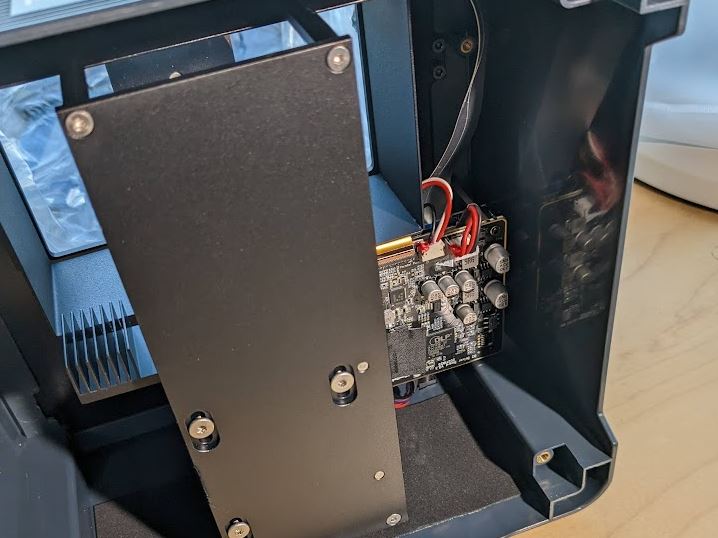
It seems like Anycubic does not produce the optical engine (marketing speak for optics and illumination) and driver board in-house, but contract it out to a company called eViewTek. If we open up the bottom of the unit, we can get our first glimpse at the projection unit and the driver board.
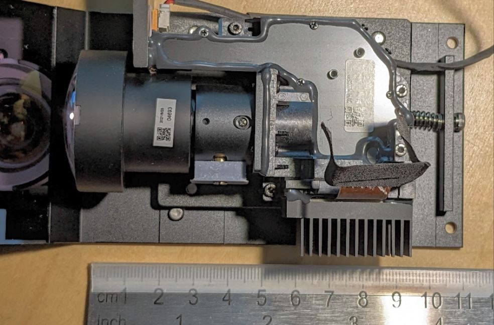
Unscrewing the optical engine by its four 2mm hex bolts we get a clearer picture at the projection unit itself. It connectors to the driver board by a flex PCB, and a separate 4-wire connector that seems to handle power for the 405nm UV LED. The flex cable has an intermediate connector that makes (dis)assembly easier.
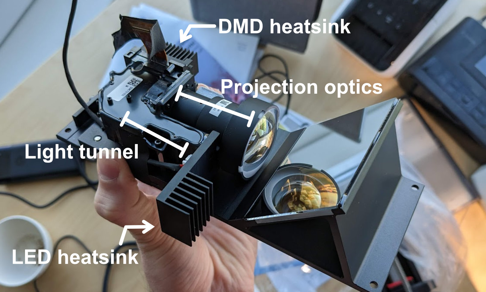
The unit itself is pretty compact, measuring about 10cm along its longest axis. It can be translated along the optical axis with a basic screw in the back and the projection lenses seem to have some adjustment too, probably to change the focal point of the optic, which should of course coincide with the bottom of the resin vat in the 3D printer. The top panel covering the optics has a thick layer of opaque glue, which probably serves to prevent any UV light leak.
The driver PCB seems to closely mirror the recommendation laid out for the DLP300s in the excellent TI documentation.
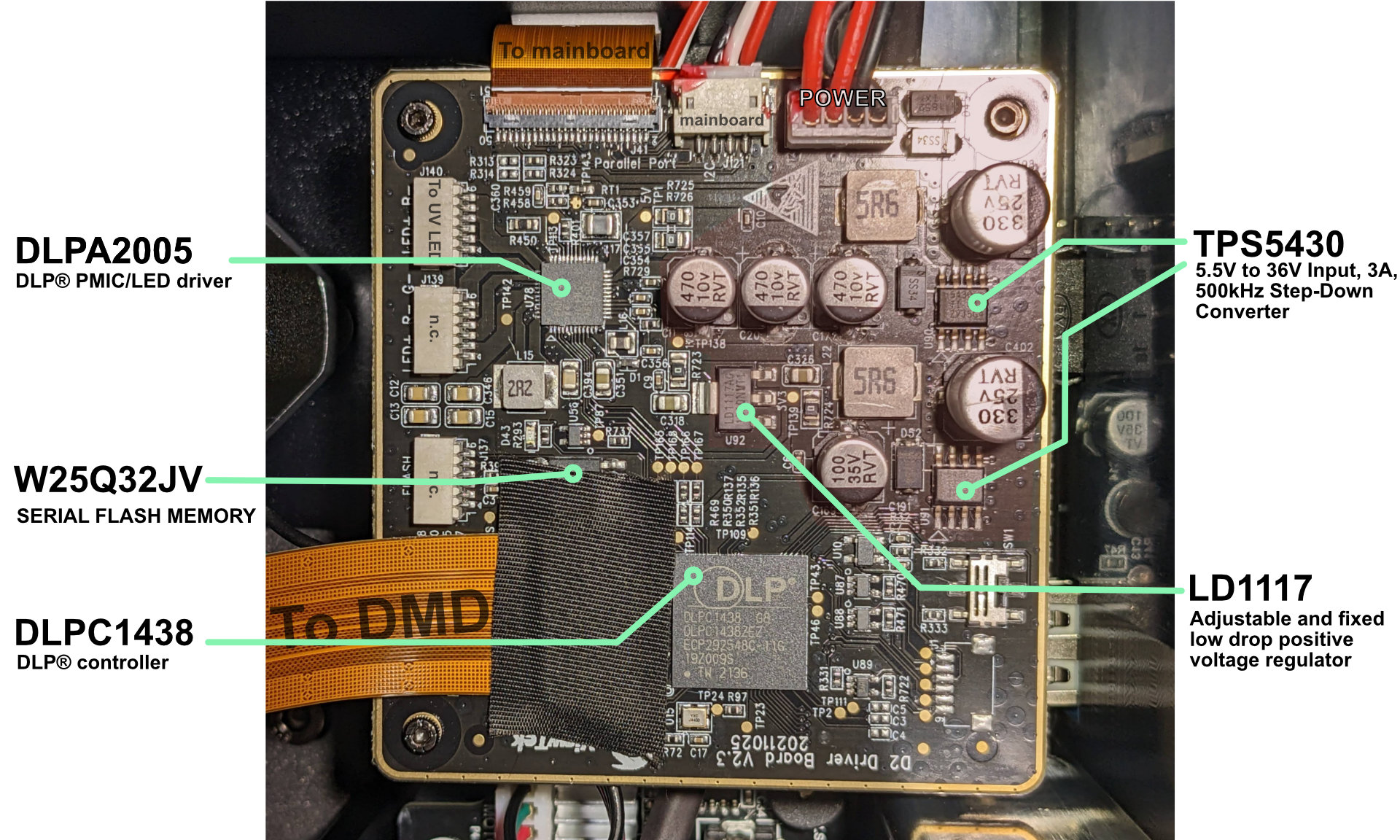
We spot the TI DLPC1438, which is the only option when it comes to driving the DLP300/1s, so seeing that is no surprise. There is some flash memory present for the DLPC1438 in the form of a winbond W25Q32JV variant. Then we spot some more boring components for power delivery such as the TI TPS5430 and the STMicroelectronics LD1117. Finally the remaining interesting IC on the board is the TI DLPA2005, which is responsible for powering the illumination and micromirror and is in tight communication with the DLP controller. There are a few alternatives from TI that we could choose instead - the DLP301s datasheet lists the DLPA2000, DLPA3000 and DLPA3005 as alternative options.
The DLPA2000 is just a lower current version of the DLPA2005. The DLPA3005 seems to be for very high current draws.
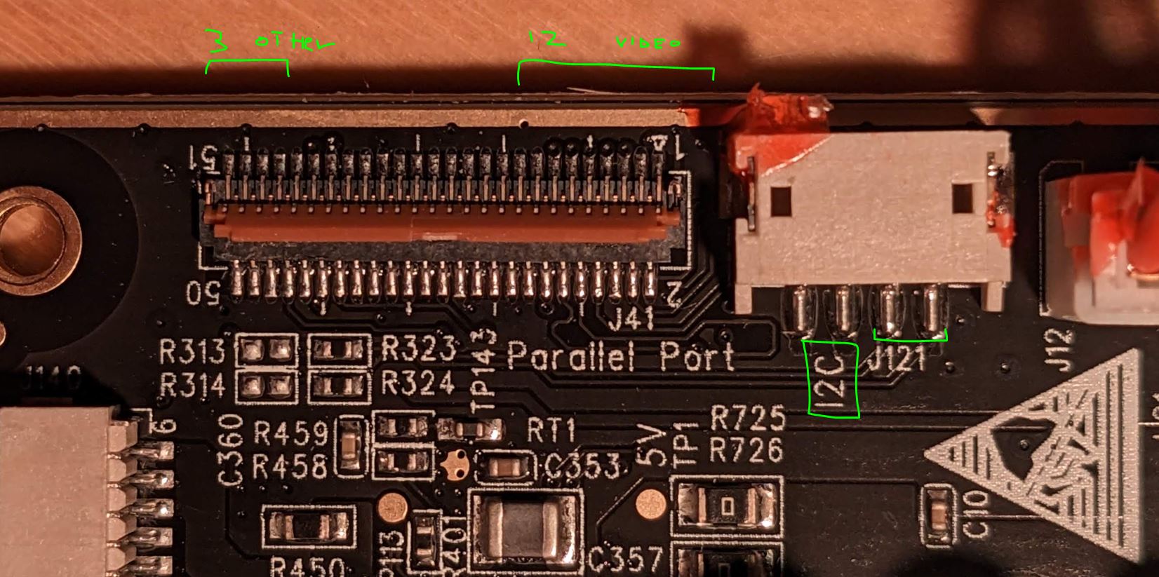
In terms of outgoing connections, we see the ribbon cable that goes to the DMD, and the wires that go to the UV LED. This leaves two connectors unconnected; I suppose they keep these in for use in RGB projectors. Not sure what the flash connector is supposed to do. In terms of incoming connectors we see a power connector, a 3-wire connector (I2C and ground I strongly suspect - you can find out more about I2C communication with the DLPC1438 in the TI programming guide) and finally another ribbon cable that all come from the mainboard. The rear of the board only has the usual collection of resistors and capacitors. In the image below I have flipped the image so that I can be overlaid over the image over the front of the board.
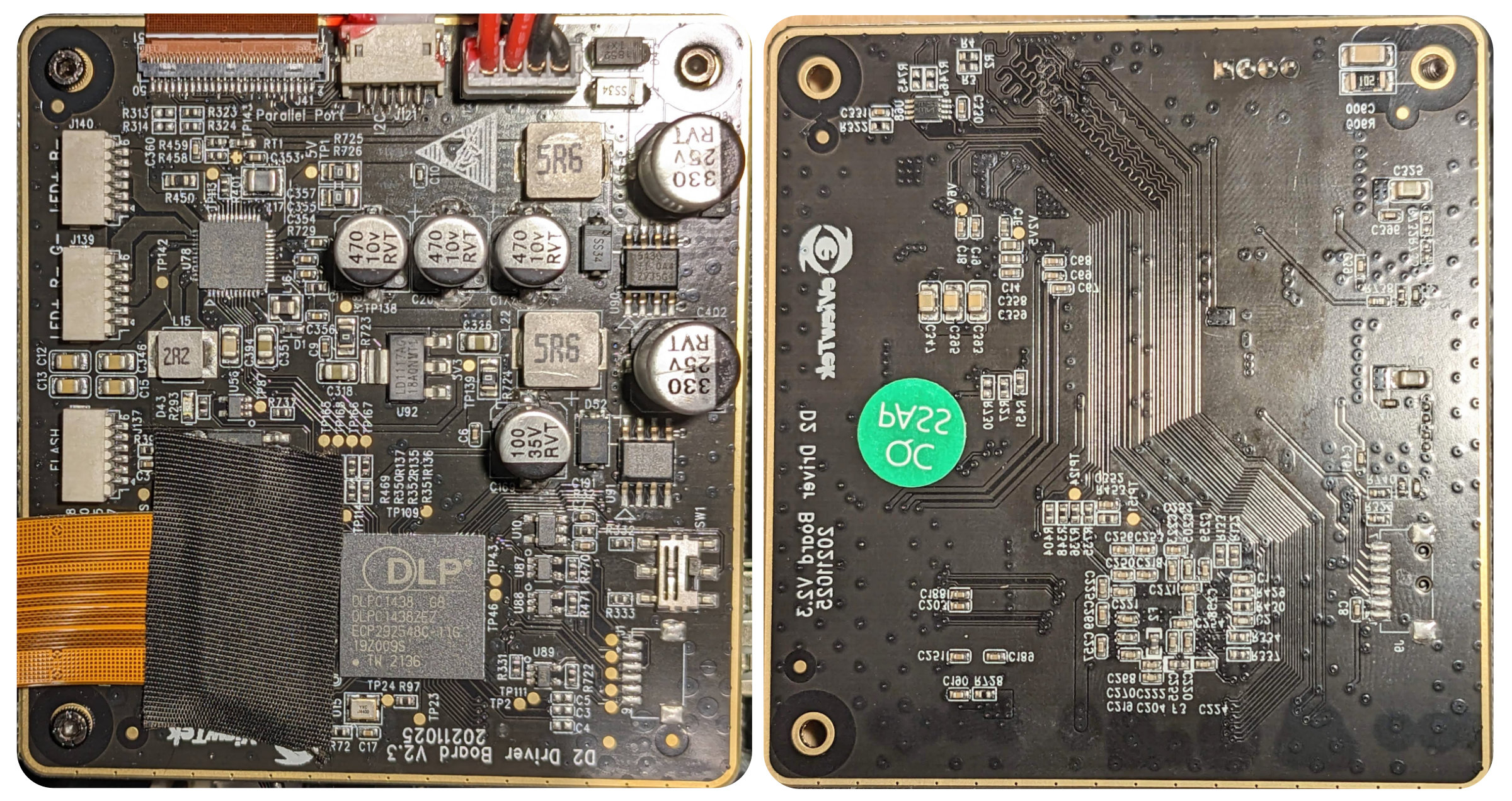
Image data FPC
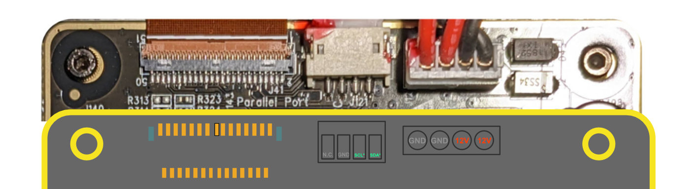
Let’s have a closer look at this ribbon cable and connector. We see that a 51-pin (0.3mm pitch) FPC connector is used. From what I can tell, only 15 traces are present (excl. grounds). Looking at the Datasheet of the DLPC1438 we see that our parallel interface needs 12 traces. 8 for the grayscale value of a pixel, and then Vsync etc. We see nicely that 12 traces seem to be grouped on the FPC.
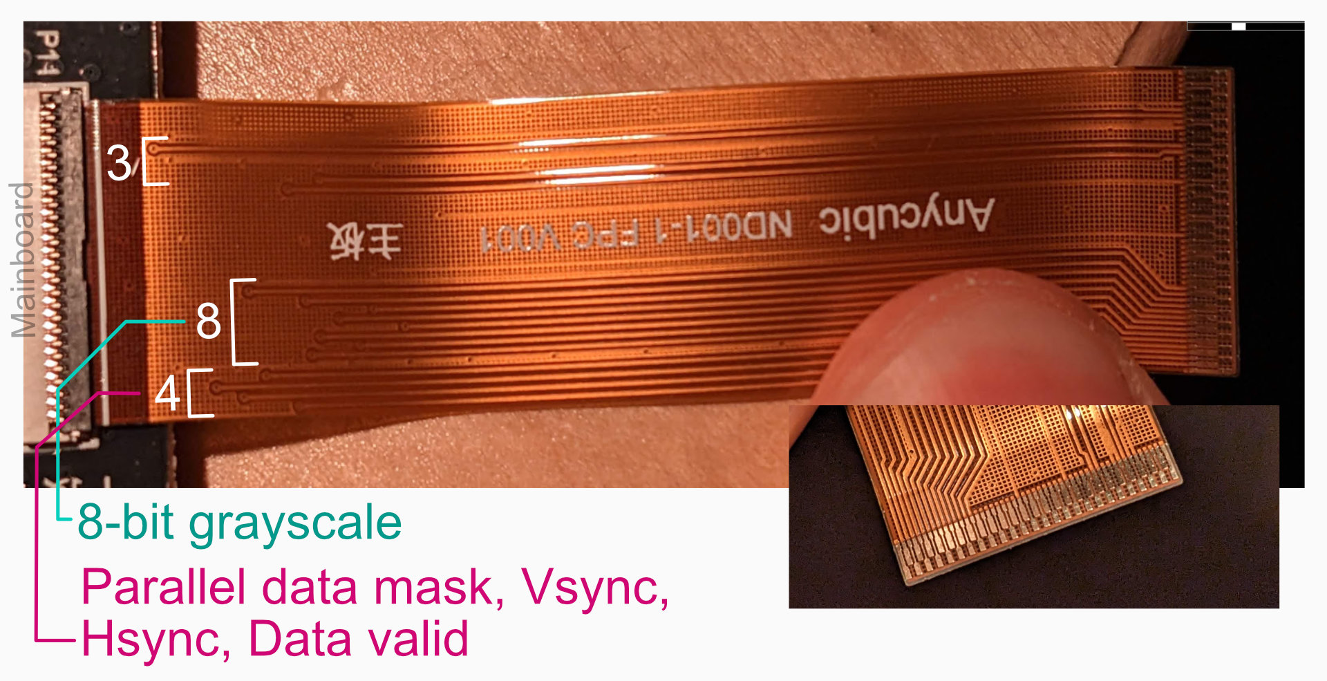
I am fairly confident I have managed to identify 14 out of 15 traces; with one having some uncertainty:
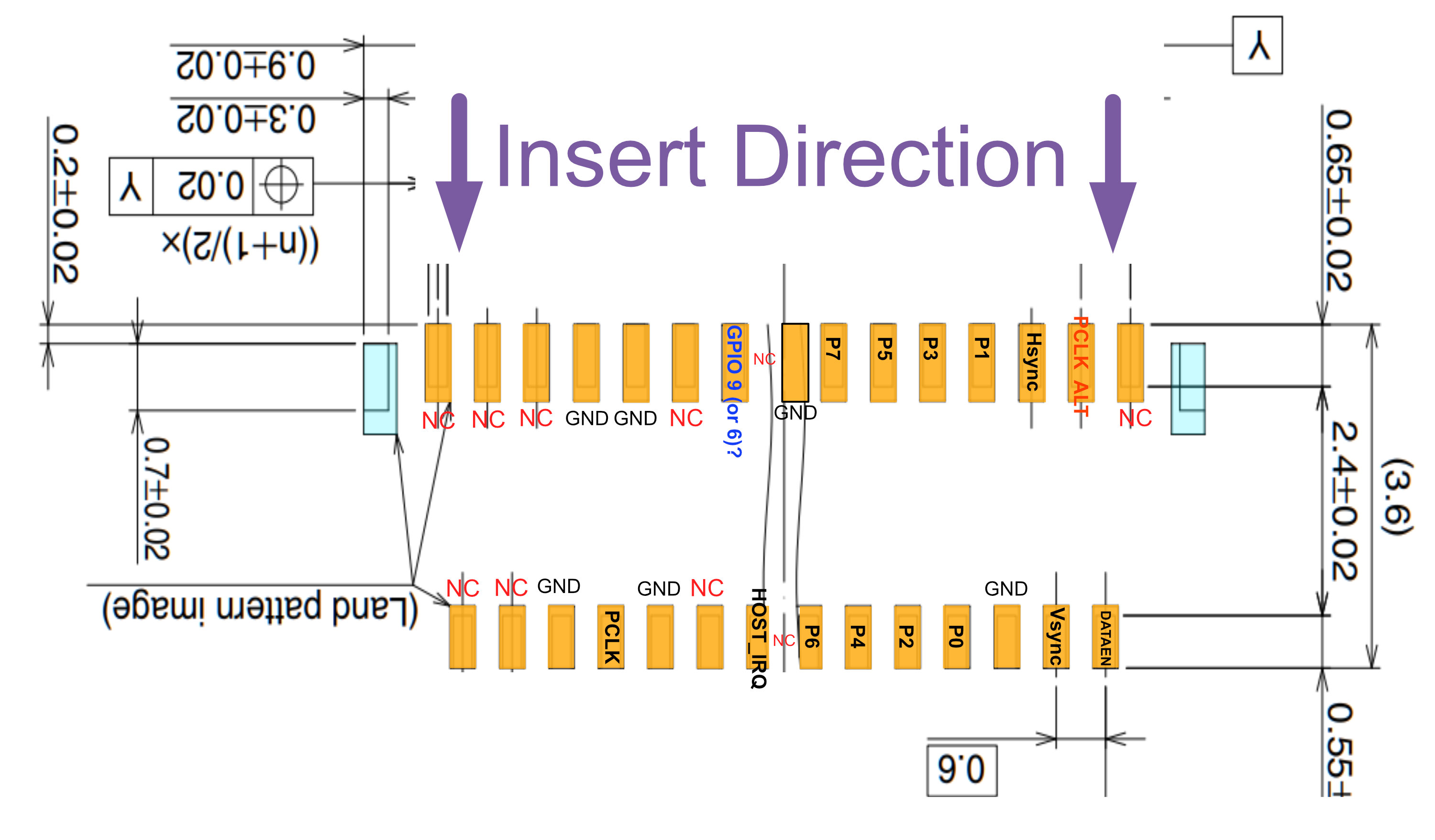
There are two PLCK lines. If we look at where these two lines meet on the back of the PCB we see that there are two ways to mount the impedance matching resistors: cyan and red. I am guessing that PLCK and PLCK ALT have different trace lengths so that one could be picked based on best transmission. Given that PLCK is only 62MHz, I am not sure if it is overkill. Still, maybe they want to re-use the designs for other high resolution projectors where the pixel clock starts to approach the hundreds of MHz.

The one pin that I am not sure of is one that is almost certainly one of the DLPC1438 GPIO pins. My guess is on GPIO_9, which indicates when a print is active. That could then be used to show the user when a layer is being exposed on the front display. But ‘System Ready signal’ (GPIO_6) or ‘normal mirror parking request’ (GPIO_8) are also candidates.
The pinout on the mainboard side is exactly the same, as the traces are pretty much straight lines. This is because the FPC is flipped (pads on opposite sides of kapton)
Controlling the eViewTek board
If you want to control the board yourself with your own IC and PCB, you could follow some of the notes below. I will be working on this for the openMLA project. There are two approaches:
Approach 1: parallel video interface
You will need to have the following 3 connectors:
- 12V power supply cable (2mm pitch, 4 pin)
- I2C connector
- FPC connector for image data (0.3mm pitch, 51 pin) - example
The 12V connector has 4 pins, two for the +12V and two for GND. Can’t really imagine a single cable wouldn’t have been enough for the device, but probably doesn’t hurt. As far as I can tell it’s a standard JST PH 4-pin 2mm connector. Orientation can be seen from images above. On the mainboard there is a 100uF capacitor to serve as (what I assume to be) some supply voltage smoothing. For some insane reason the red wires are GND, and the black ones are +12V.
The I2C connector is a bit strange. It is a 4-pin connector on the eViewTek board side, but 3-pin on the mainboard. It seems like one of the pins is GND, the other two are 3.3V. I have not been able to confirm what the bus frequency is. On the eViewTek board they get level translated by a TXS0102 to something like 1.8V. Unfortunately the level shifter hides the SCl and SDA traces so I am not 100% sure if SDA/SCL should be swapped atm.
The layout of the 51-pin FPC connector can be reviewed in the section above. The mainboard has a Vsync signal at a frequency of 67.5 Hz, which seems a bit excessive for 3D printing. The Hsync rise signal has a period of 20us (50KHz). That would put a lower bound on PCLK of 50*1240 = 62MHz. The measured value is 62.2-62.5MHz, so that checks out.
Approach 2: SPI+ I2C communication
It was pointed out to me that it is also possible to send the video (and some other commands) through an SPI interface to the DLPC1438. The DLPC1438 has an on-board FPGA which then interprets the video data sent over SPI and will expose that with the right timing to the rest of the system.
An alternative approach which is more flexible on the implementation side (requiring only I2C and SPI on your controller) is approach 2, where we do not have to implement the parallel interface or deal with the fiendish 51-pin connector (for the most part).
You will need to have the following 3 connectors:
- 12V power supply cable (2mm pitch, 4 pin)
- I2C connector
- Connector that ends up a JST SH 6-pin male connector
For point (1) and (2), see the previous section. For point (3), note that this cable plugs into the connector on the left side of the board in the board image above labelled ‘FLASH’. The pinout of the connector (top to bottom, based on main board image):
- CSZ0
- MOSI
- MISO
- (S)CLK
- GND
- +3.3V
This then connects to SPI0 lanes of the DLPC1438. If more information is uncovered I will add it here or add it to the controller board that I am working on.
Miscellaneous
The mainboard of the photon ultra can be viewed in more detail here in the official retail image from Anycubic. The CPU is a GigaDevice GD32F307 (ARM Cortex-M4). There is another IC that seems to sit in between the CPU and the display output connector - it might be a small FPGA, but I cannot verify this at the moment as it is covered by a heatsink.
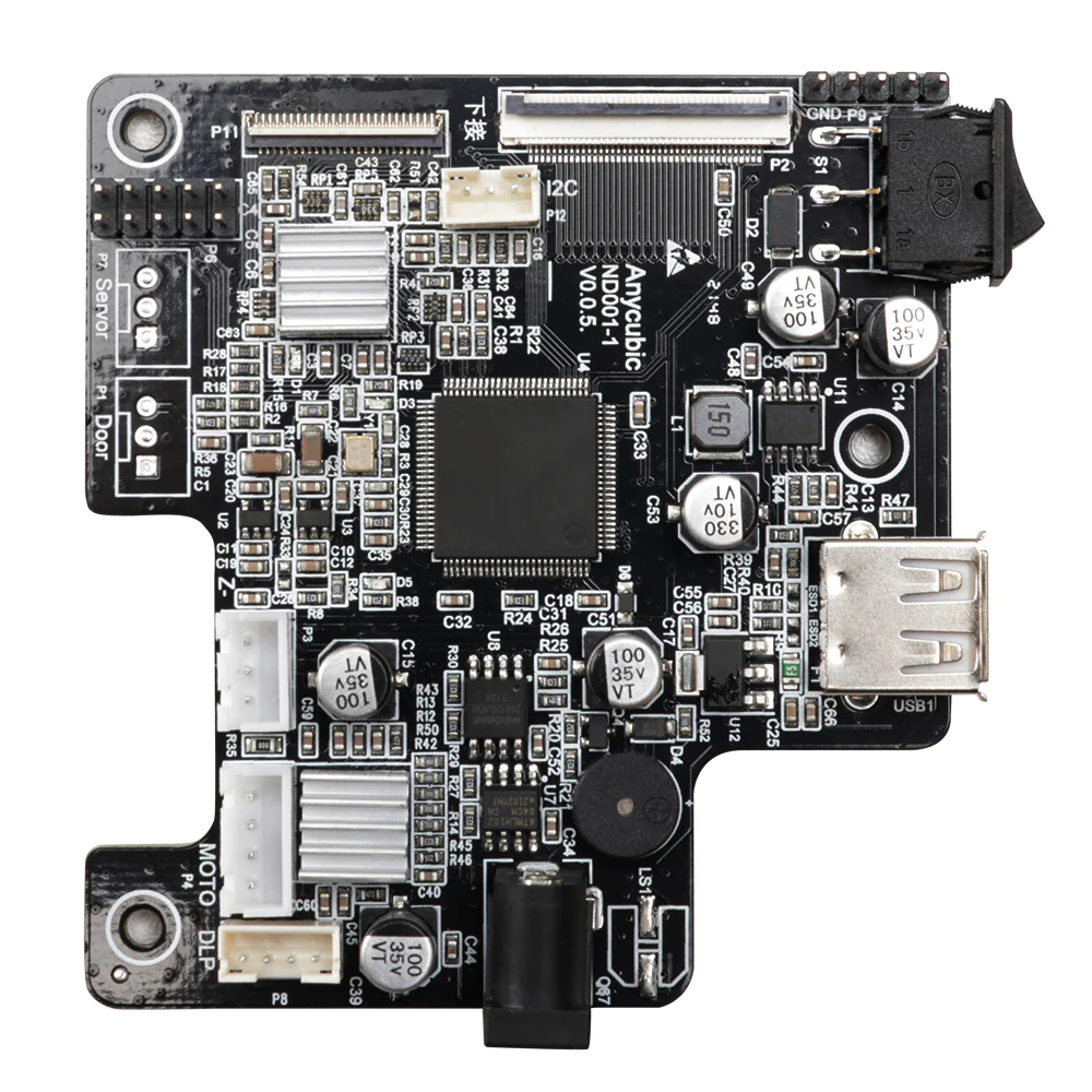
Some other interesting things to note about this board is that the title of the board is ‘D2 Driver board V2.3’. This seems to refer to the internal name for this optical engine by eViewTek. I wonder why they didn’t call the first version of this 3D printer the D2. Secrets of the marketing department, I suppose.
While the chip in the Photon D2 is undoubtedly the same unit, there are some notable differences between the units, based on the repair video mentioned earlier. In the repair video we see an extra 4-wire cable connector to the optical engine. In addition, the driver board has been completely overhauled and instead of a flex cable for data exchange with the main board there are now just a few more regular copper wire connectors. I suspect this extra connector is needed for the XPR unit that ‘increases’ the ‘resolution’ of the projected image by a factor of 4.